VariCAD 2020 v1.09
VariCAD 2020 v1.09 | 176 MB
VariCAD is 3D / 2D CAD software primarily intended for mechanical engineering design. The comprehensive CAD software enables designers to quickly create, evaluate, and modify their models. The software is sold as one "fully loaded" package, with all features and functions, for one very affordable price. VariCAD delivers an excellent performance-to-price ratio, making it one of the smartest choices on the market today.
User Interface and System Environment
VariCAD's Graphical User Interface (GUI) has been designed to allow quick and intuitive 3D/2D orientation. It has been carefully tailored and tuned to reflect the thought process of a designer, so that ideas can be captured and communicated with a minimal number of steps. All commands were created with a focus on ease of use.
You can start by creating a 3D model and then use it to automatically create drawings files, or you can draw only in 2D. Designing in 3D is generally more "natural," in that it closely represents actual parts and assemblies. The 3D approach is usually more intuitive than 2D drafting. Models created in 3D are easily converted into conventional 2D documentation. VariCAD provides tools for 2D updates after changes of 3D models.
3D Modeling
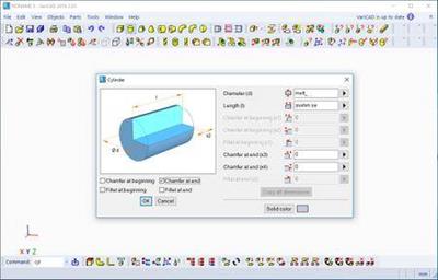
VariCAD provides a library of basic 3D shapes (like a box, cylinder, cone, etc.), which are easily modified by editing their dimensions. Solids can be created also by profile rotation, extrusion, or lofting. More complex tools include rotation blending between two profiles, lofting between a circle and rectangle or between different profiles, and creation of helical surfaces.
Solids can be added or subtracted, thus forming Boolean trees representing real mechanical parts. Boolean operations have options of automatic trimming (so called selective Boolean operations). Predefined operations like drilling of holes, face milling or groove milling are also available. Edges can be rounded or chamfered. VariCAD provides a lot of possibilities of solid transformations or their editing. Also, you can easily edit Boolean trees - either selecting solid parts from 3D, or selecting them from a list displaying structure.
Parameters and Geometrical Constraints
Although you can comfortably transform solids or their parts, you can optionally define geometrical constraints. Once defined, constraints allow you "to stick" object at defined location. More exactly, you can remove degrees of freedom of constrained objects. If other objects are changed or transformed, constrained object changes its position automatically. For instance, if you constrain a groove to the end of a shaft and the shaft length is changed, the groove remains in constant distance from the end edge. Constraints can be defined among elements of a solid, among entire solids or within a 2D profile creating a solid (for instance, by extrusion).
Whenever you enter a dimension of solid, a distance in constraint or dimension in 2D profile used for solid creation, you can optionally use parameter or even a mathematical expression containing parameters. Changing parameter values, you can change shapes or locations of solids.
3D Assemblies and Groups
VariCAD also provides tools for assembly support. If the link between a part and assembly is defined, any changes made to the part file are reflected in the assembly file and vice-versa. Linked copies of solids can also be defined (so called identical solids). In such case, editing of one object causes update of all its identical copies. Solid groups can be defined as well, making selection and visibility changes simple, for multiple objects.
Crash Tests (Interferences)
One excellent feature of 3D modeling is component interference checking. VariCAD can check 3D assemblies for possible collisions (overlapping volume) between components.
Calculations
VariCAD can calculate 2D section area, surface area, volume, mass, center of gravity, and moment of inertia. Mechanical parts calculations are also included - for standard parts used every day by mechanical designers. There are calculations of tension and compression springs, pre-stressed bolted connections, pins and parallel keys, grooved shafts, bearings, beams under combined stress (bending and torsion), spur and bevel gearing geometry, and belt drives.
Surface Development (Sheet Metal Unbending)
VariCAD can also create developed (unbent) surfaces of 3D solids or sheet metal parts. The XY coordinates of developed surfaces can be saved into a text file for further processing. You can input bending coefficients in order to customize your calculations, to reflect material and technology.
Mechanical Part and Symbol Libraries VariCAD contains libraries of standard mechanical parts (ANSI, DIN), such as bolts, nuts, pins, plugs, cotters, gaskets, bearings, rolled and drawn shapes, and hydraulic, pneumatic, and electrical symbols.
3D - 2D Export
3D models are easily converted into 2D drawings to produce conventional drafting documentation. You can create 2D views of one or more selected solids by defining the views in 3D. In addition, you can also export specified sections. VariCAD supports updates of a 2D drawing after changes in 3D.
2D Drawing and Editing
Drawing functions are optimized for easy use in engineering. Some handy features of 2D drawing include: automatic detection of objects and snap points, numerous snap modes, auxiliary construction lines, Ortho mode, rectangular grid, drawing layers, block creation, hatching with automatic border detection, advanced dimensioning, finish symbols, welding symbols, tolerance symbols, and many more. You can draw in millimeters or in inches.
BOM and Title Blocks
VariCAD provides tools for maintaining the data structure of the product. There are links between attributes of parts and content of title blocks. You can create a bill of material (BOM) from an assembly, or easily modify the database using commands like mass attribute changes, sorting of information, etc. Each part can contain attributes, like name, type of material or supplier. Such data can be used for material requisitions, creation of bills of materials (BOM), filling of title blocks, or other purposes.
The data structure of the product (BOM) can be exported into other systems or into a spreadsheet. A mask is used for BOM customization; you can modify it exactly according to your needs. Mask defines usage of solid or assembly attributes, working with title blocks, methods of data exports from BOM etc...
Compatibility
VariCAD can interchange files with other CAD systems. You can export STEP (3D), STL (3D), IGES (3D), DWG (2D), DXF (2D) files, and import STEP (3D), DWG (2D), DXF (2D). The files can be converted individually or in batch routines, thereby converting multiple files in one step.
VariCAD 2018
This version supports 3D mouse under Linux. VariCAD commands are available from 3D mouse keys. Next new features are isometric views in 3D mode and 2D objects created from data loaded from *.csv files or, generally, text files (files containing XY coordinates). User interface contains virtual numerical pad available for values input, and rebuilt dialog panels used for definition of basic solids (like box, cylinder...). The new version has improved parts of 3D kernel, including input/output of STEP files.
System requirements
Hardware and software recommendations for large assemblies (aprox. thousands of parts):
Multi-core processor, e.g. Intel Core i5-4460
8 - 16GB RAM, for extremely large data more
Graphic card with hardware support of OpenGL 4 graphics (NVIDIA GTX/Quadro graphics chip, 2GB RAM), e.g. GIGABYTE N960IXOC-2GD
5-button mouse with the scroll wheel
64-bit operating systems: Microsoft Windows 7, Windows 8/8.1, Windows 10
Home Page -
DOWNLOAD LINKS: